GMP - Microwaves
Good Manufacturing practise (GMP) for Industrial Microwave Plants
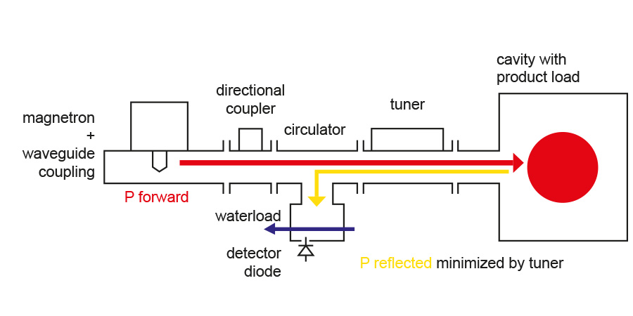
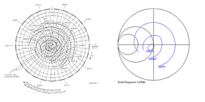
The schematic design of a microwave system is shown in figure 1. The magnetron is installed on a waveguide launcher. The electromagnetic energy is guided within the waveguide structure and coupled into the applicator (cavity). The amount of reflected electromagnetic energy depends on the dielectric properties of the heated product and the dimensions of the cavity. In order to achieve the best possible efficiency, the amount of reflected electromagnetic energy can be minimised by using a tuner.
The installed circulator acts as a load protection for the magnetron. The quality of the circulator used determines the absorption of the reflected energy by the water load.
If no circulator is used, the reflected energy moves back to the magnetron. This results in a shortened durability of the magnetron and power output of the magnetron is reduced as well (see figure 2). This causes the amount of power needed for the process to be unstable and the process becomes non-reproducible.
Due to this background it is necessary to protect magnetrons by using circulators.
High-end circulators possess an isolation of better than 20dB (typical 21-26dB).
The advantages of a GMP microwave system are:
- Magnetron will last for its specified life-time
- The incident power of the magnetron for the system is constant (Magnetron is operated within its specs)
- By using a directional coupler or a detector diode, the reflected power can be measured. With the measured incident power of the magnetron, a calibrated microwave system is able to calculate the power absorbed by the product.
![]()
The given microwave power of an industrial microwave system has to be measured and labeled according to the international standard IEC60307.
Disadvantages of not protected Multi Systems
In terms of understanding the disadvantages of a system using a larger number of single magnetrons without protection and tuning, figure 3 shows the design of a multimode cavity with 4 magnetrons, coupling directly into the cavity.
As a three-dimensional mode distribution travels within the multimode cavity (the distribution depends on load condition of the cavity) the E field distribution in figure 3 is shown in the cross section plane of the 4 magnetrons.
Due to the value of the standing wave ratio of the E field at the magnetron antenna location, the magnetron faces different load conditions resulting in different reflections.
Therefore, the actually required power for the process is determined by undefined changes which finally result in a non-reproducible process.
During operation of the magnetrons in figure 3, a condition like moding may occur. The magnetrons consume higher anode currents which cannot be maintained by the power supplies. This may cause damage to both, the magnetrons and the power supplies.
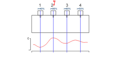
Figure 3. Design of Microwave System without Protection and Tuning of 4 Magnetrons in a Multimode Cavity.
Microwave Heating
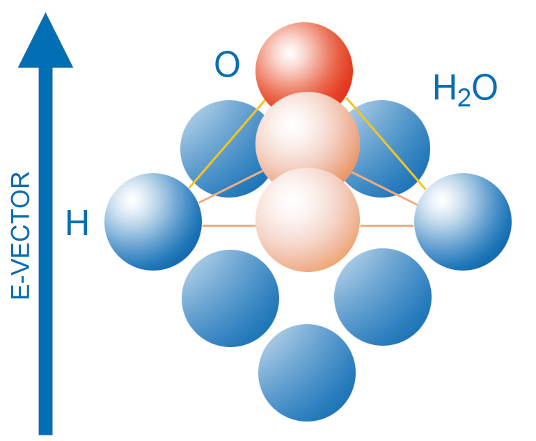
By using microwave energy, heat is generated inside the product volume by directly transforming the electromagnetic energy into molecular kinetic energy.
Püschner Microwave Heating Advantages
Costs
- saves energy because only the product is heated
- compact units save space
- limiting factor "heating" on the process line is eliminated
- flexible modular design
- reliable with an intelligent service and maintenance concept
- environmentally friendly
Quality
- gentle on the product because of total volume heating
- high control and process speeds
- minimal delay before ready to use
- rapid heating to operating temperature
- uniform heat distribution