
Basic Calculations
Essential elements for generating heat in a volume
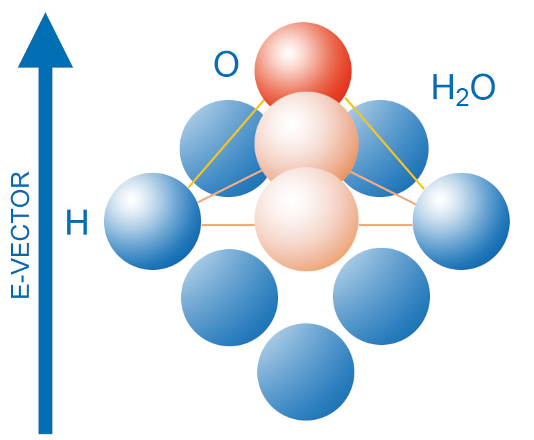
The essential elements for generating heat in a volume are the electric field strength of the microwave field, the frequency, and the dielectric properties of the material represented by its microwave power dissipation (equation (1)).
![]()
P´´´ = volume energy density measured in W/m 3
f = operating frequency measured in Hertz
εo = permittivity of free space = 8.85 x 10 -12 AS/Vm
ε r´´ = dielectric loss factor = imaginary part of complex permittivity
Ε = electric field strength measured in V/m (effective value)
The loss factor depends on both frequency and temperature.
As a rule it can be said: The higher the loss factor of a substance, the better the substance can be heated in a microwave field. Water and all aqueous substances possess a high loss factor and, therefore, absorb high frequency energy and microwave energy exceedingly well. Depending on their absorption behavior towards microwave radiation, materials can be classified into three groups:
- absorbers, e.g. water ( εr’’ =12 at 25° Celsius), aqueous substances (practically all foodstuffs), diverse sorts of plastics
- transparents, e.g. porcelain quartz glass ( εr’’ = 0.0023), Teflon
- reflectors, e.g. metal, graphite
Down to a loss factor of about εr’’ = 0.01 substances can still be heated in a microwave field. If the loss factor is below this value, there might still be the possibility to blend in additives with higher loss factors which, however, should not change the desired properties of the substance.
For special applications, exceptionally high field strengths can be generated within the heated materials after carrying out specific optimization procedures.
If the loss factor of a substance changes too much in relation to the temperature, irregular heating might result.
For example, on thawing a frozen material the thawed parts absorb microwaves more intensively than the frozen areas.
The following example illustrates the use of equation (1) with typical input values to give an indication of the power density values which are usually encountered in practical work. A flask filled with water (temperature 50 °Celsius, εr’’ =5.1) is placed in a heat chamber and exposed to a mean field strength of 2 kV/m. Here, the dissipated power density within the water will amount to approximately 2800 kW/m3 = 2.8 W/cm3 at 2450 MHz.
Hence, a heating of water ensues according to
![]()
The field strength distribution in the heat chamber, i.e. the field strength as a function of spatial coordinates, depends on the microwave generator used, the quality, number and arrangement of the microwave coupling sites, the geometry of the chamber, the geometry and physical properties ( εr’’ ) of the material to be heated, and the reflection characteristics of the surrounding metal walls.
In research and development, attempts have been made to predict the field strength distribution with the aid of numerical procedures. However, this undertaking proves to be rather difficult as refraction and diffraction phenomena occur when the electromagnetic waves penetrate the material. Depending on its geometric shape, power concentrations might occur in corners and on edges as well as in particular interior areas volume (lens flares). On account of the complexity within its interrelationships among these parameters, calculations of the field strength distribution are possible only for simple and ideal arrangements. Therefore, the design of a heat chamber for a microwave heating plant still depends strongly on experience and trial runs.
Microwave Heating
By using microwave energy, heat is generated inside the product volume by directly transforming the electromagnetic energy into molecular kinetic energy.
Püschner Microwave Heating Advantages
Costs
- saves energy because only the product is heated
- compact units save space
- limiting factor "heating" on the process line is eliminated
- flexible modular design
- reliable with an intelligent service and maintenance concept
- environmentally friendly
Quality
- gentle on the product because of total volume heating
- high control and process speeds
- minimal delay before ready to use
- rapid heating to operating temperature
- uniform heat distribution